|
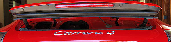
| Ripped bellows easily can be separated reducing tension between the upper and lower retaining bars before removing them. |
|
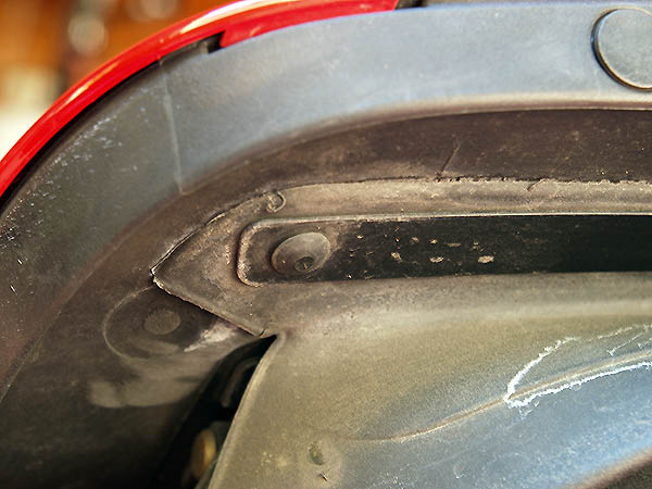 |
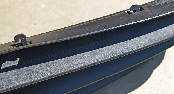
NOTE: The bar is designed with hooked flanges (see below) that hold the bar in place against the inside engine cover. By shifting it to the right, you will disengage the flanges from their seating.
|
 |
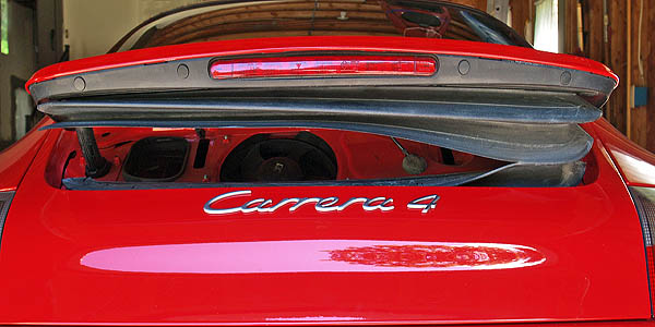
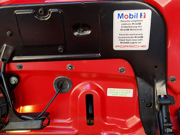
The lower bellows is secured to the engine lid by a metal bar that is to the interior of the bellows. This photograph was taken after ripping apart the old bellows. Normally, the lower metal bar would not be visible; the bellows block the view. |
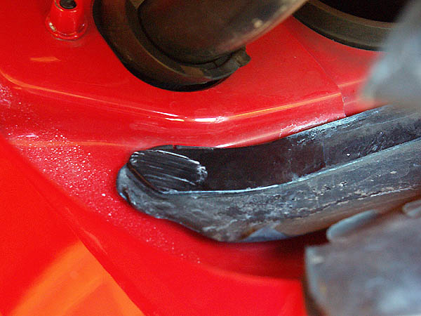
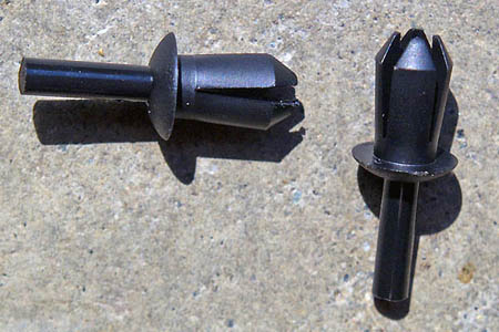
The bottom of the bellows also is held in place by a metal retaining bar. This bar has
pins that project downwards and are secured with round snap nuts in the engine lid. There
are eight (8) snap nuts that must be removed (four [4] are shown in the image to the right).
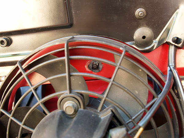
One snap nut is beneath the fan assembly.
NOTE: If you lose a snap nut, it may be possible to find a near equivalent at your local body shop. But, these probably will not be metric. There is a close English equivalent hole diameter. |
 |
 |
|
| The upper metal retaining bar is pictured with the flanges facing up, as they will be reinstalled. The lower metal retaining bar is pictured with pins facing down, as it will be reinstalled. | 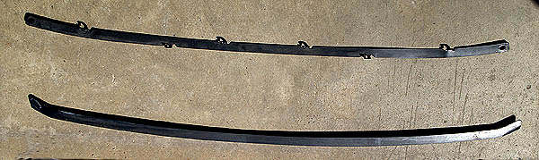 |
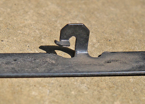 |
This image shows the design of the upper retaining bar flange. |
|
 |
 |
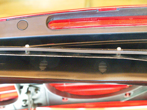
NOTE: It may take some adjustment of the bellows right or left to align the holes before the rivets are inserted and secured. |
Insert the lower metal bar through the holes in the bellows, and then place the pins through the holes in the engine lid to be secured by the snap nuts. Note that in the photograph to the right that the bellows have been turned upwards to show the pins in the metal bar (lower metal piece; pins appear as white dome structured) inserted through the bellows. When completing this step, the retaining bar will not be visible because it will be on the inside of the bellows. |
 |
|
|
and
 |